No products


BLSD4875DC-2Q-H
BLSD4875DC-2Q-H
New product
48V, BLDC Servo Driver. 18.75~75A. Square Wave, Hall Input. Speed or Torque Loop control.
Contact cs@machmo.com for exact leadtime!
Data sheet
| Rated Current | 18.75 ~ 37.5A |
| Peak Current | 37.5 ~ 75A |
| Input Voltage | 37 ~ 56VDC |
| Operating Temperature | -10 ~ 45 ºC |
| Pulses Frequency | 15 kHz |
| Hall Sensor | 60º or 120º |
| Control Methods | Speed Closed Loop or Current Closed Loop |
| PG | 24p @ 8-pole |
| SV Ramp Time | 0.1 ~ 10 Seconds |
More info
Square Wave BLDC Driver for use with our SV060AS-03 & SV080AS-01 Servo Motors.
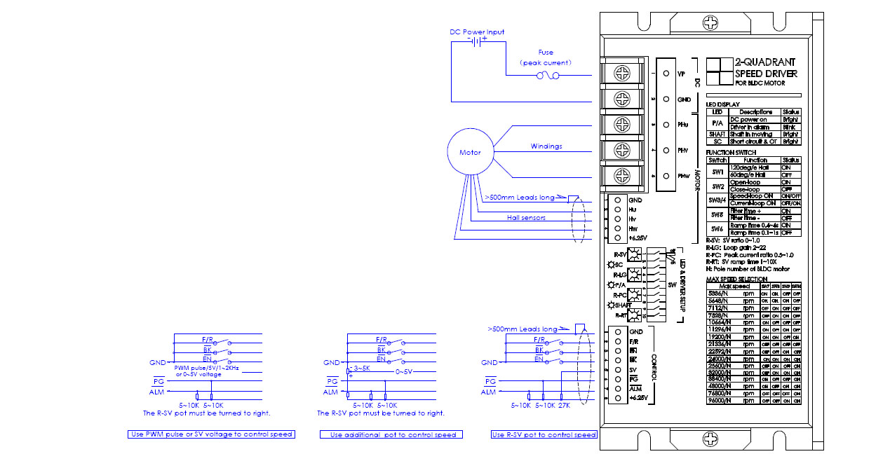
 1.Control signals:
F/R—–H or Open=Forward, L or Close=Reverse
EN——H or Open=Disable, L or Close=Enable
BK——H or Open=Running, L or Close=Brake
SV——0~5V speed reference(112K input resistance)
PG—–Speed pulse output(OC)
ALM—Alarm output(OC)
2. Signal wire:
Control signal cable and hall sensors cable can not be tied together with windings cable, otherwise, it will take interference. The long wire should be shielded wire.
3. Alarm conditions:
a. Hall sensor signals are not correct.
b. LV or OV for 1~3S.
c. Short circuit and Over temperature of case (80℃)..
d. Over load for 5~6s continuously.
e. It can be reset by Turn-Off-On DC Power or Disable the driver once.
4. LED indicator:
SC——–Bright=Short circuit , Dark=driver is OK
P/A——-Bright=Driver is OK, Blink=Driver is in alarm
SHAFT—-Bright=Motor shaft is moving, Dark=Motor shaft is in static
5. Braking operation:
The motor speed must be less than the safe brake speed Ns when you brake the motor.
For Y windings, Ns=√3 x Ip x RL x N/ (2x Vp)
For △windings, Ns=IP x RL x N/ (2 x √3 x Vp)
Ip=Peak current(A), RL=Line to line resistance of windings(Ohm)
N=No-load speed(rpm), Vp=Rated voltage(V), Ns=Safe brake speed(rpm)
6. Safe F/R:
If you change F/R of the driver rapidly, it will stop the power stage and motor will be free until the speed is detected as zero,and then to drive in correct direction. This means smooth reverse.
7. Safe start:
If the motor speed is not detected as zero at power on, the driver will be free until the motor speed is zero.
8. Drive setup by pot and switch:
R-SV pot=SV voltage ratio, R-LG pot=Loop gain, R-PC=Peak current ratio, R-RT pot=Ramp time
SW1=60/120 Hall sensors, SW2=Open/Close loop, SW3,4=Speed/Current loop, SW5=Loop filter time, SW6=SV ramp time setting, SW7,8,9,10=Speed range setting.
9. Peak current selection:
Ip>=2xIr or Ip>=4xPo/Vp, Ip is peak current of driver(A), Ir is rated current of motor(A)
Po is rated output power of motor(W), Vp is rated voltage of driver(V)